Radha Krishna Ganti,
Associate Professor,
Department of Electrical Engineering, Indian Institute of Technology Madras
Email: rganti@ee.iitm.ac.in
About Author: Radha Krishna Ganti is an Associate Professor at the Indian Institute of Technology Madras, Chennai, India. He received his B. Tech. and M. Tech. in EE from the Indian Institute of Technology, Madras, and a Masters in Applied Mathematics and a Ph.D. in EE from the University of Notre Dame in 2009. He is a co-author of the monograph Interference in Large Wireless Networks (NOW Publishers, 2008). He received the 2014 IEEE Stephen O. Rice Prize, and the 2014 IEEE Leonard G. Abraham Prize and the 2015 IEEE Communications society young author best paper award. He was also awarded the 2016-2017 Institute Research and Development Award (IRDA) by IIT Madras. In 2019, he was awarded the TSDSI fellow for technical excellence in standardisation activities and contribution to LMLC use case in ITU. He was the lead PI from IITM involved in the development of 5G base stations for the 5G testbed project funded by DOT.
Five Key Technologies of 5G RAN
Key words: 5G, massive MIMO, OFDM, SCS, ITU, 3GPP
5G has been the center of the global news, geo-political battles for a variety of reasons in the last few years. Finally amid much fanfare 5G is being deployed across the world. In India, the spectrum has been allocated and we should soon see 5G networks in action. The development of 5G has started about a decade back with ITU identifying the vision of IMT-2020 (the technical name for 5G). This was followed by ITU defining the key-performance indicators (KPI) of 5G, followed by the development of technologies, evaluation, and ratification of the 5G technologies by ITU. This development story of 5G in the last decade is exciting (to say the least), and India’s journey in the 5G standards is worth a blog post by itself (more about this in subsequent posts). This post is about the technical aspects of 5G, hopefully cutting the veils of PR and highlighting the key technologies that are driving 5G radio networks.
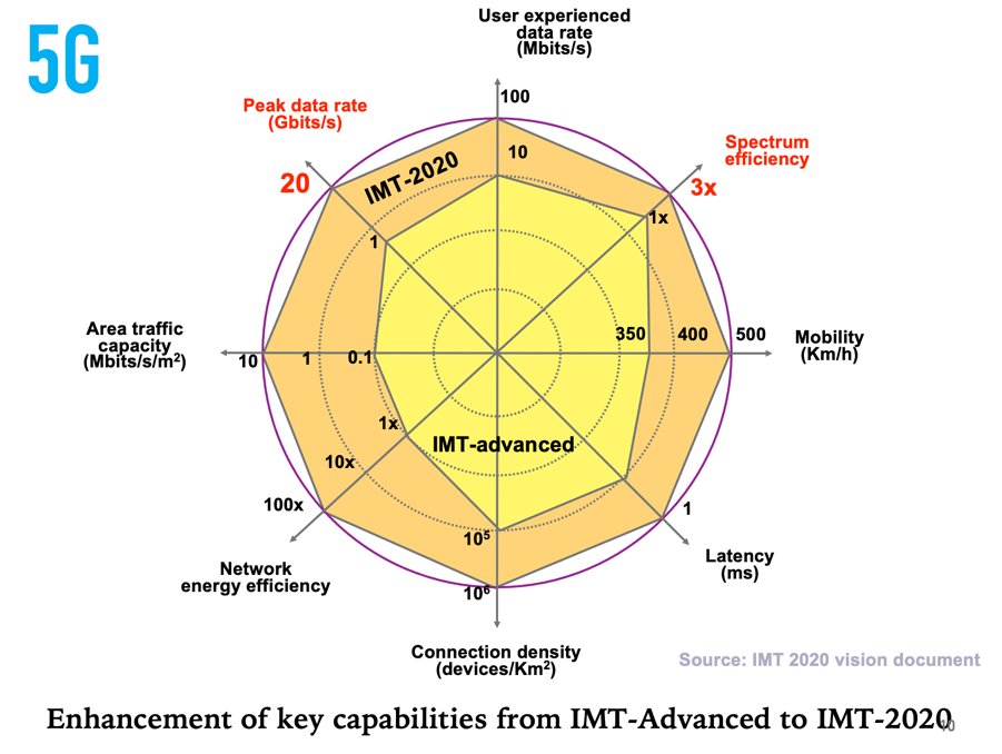
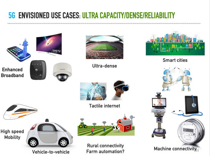
When we speak of 5G, it is the standard developed by 3GPP that we generally refer to. 3GPP is a consortium of companies and institutions across the world that has been developing cellular standards from 3G onwards. They have developed the 5G standard to meet the requirements set by ITU and as an evolution of 4G (LTE) standard. The 5G standard was designed to meet the ICT requirements of the world for the next decade. The popular octagon (see the side figure) from ITU summarizes the developer’s vision of 5G. From the figure we see that 5G should outperform 4G in almost all the metrics. It is supposed to be a super-charged update of LTE-advanced which can provide gigabits per second data rate, low latency, large energy efficiency and even support videos on bullet trains! In addition, 5G was envisioned to meet multiple use cases ranging from watching videos on cellphones, to controlling farm equipment on 5G, remote operations and smart cities. These variety of use cases require 5G to provide very high data rates, as well as provide low-latency and very high reliability.
The 5G NR standard consists of two main parts: the Core network and the RAN network. The core network takes care of data flows, connectivity to the internet, authentication, billing among other things. 5G core has significant enhancements (such as slicing, MEC) compared to the 4G core which enable a lot of the above enhancements. However, in this post we will focus on the RAN (Radio Access Network), which deals with the Radios and antennas that you see on the top of the towers that convert the data bits (coming from the core) into waveforms, process these signals and transmit over the air to communicate with the cellphones and vice-versa.
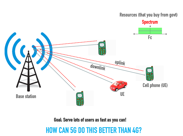
5G RAN is responsible for talking to multiple cellphones, providing connectivity and coverage. 5G is a cellular system and the RAN consists of multiple base stations with antennas sitting on the top of the tower. Each base station serves multiple users in its cell (serving area) in the allocated spectrum. The base station transfers data to the cellphones (downlink) as well as receives data from the cellphones (uplink). A 5G base station must not only serve cellphones but also machines, cars and any other 5G device. The goal of the 5G system is to serve lots of users as fast as possible while being very efficient in the usage of the spectrum. How can 5G do this better than 4G? How is it fundamentally different from 4G? What enables 5G to meet the KPI shown in the ITU-Octagon? We will now look at five key technologies, that in my view enabled the RAN to meet the 5G KPI and support all these new use cases.
- Better Signals: OFDM
- Efficient transmission: Massive MIMO
- Larger Bandwidth: Mmwave frequencies
- Faster response: Low-latency design
- Green signaling: UE oriented design
1 Better Signals: OFDM
A BS must serve multiple users at the same time. For example, in a 500-microsecond slot, a 5G BS might typically serve about 15—20 users. How is it possible to server so many users efficiently in such a short interval?
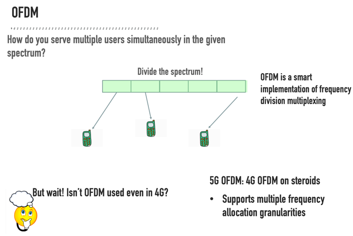
A BS can serve multiple users using two different techniques: Separate the users in time or frequency. 5G does both. Serving users in time is a straightforward concept that has been there from GSM (2G). Essentially time is sliced, and different users are served in each slice. Serving users by using only time-multiplexing (without frequency multiplexing) might lead to larger delay as only a single user can be supported at each time instant. Also, a typical 5G deployment BW is about 100 MHz and providing 100 MHz to a single user might be an overkill as the users might not require such high data rates. So, it makes sense to also divide the allocated bandwidth (BW) and serve multiple users simultaneously using frequency multiplexing.
How can one split the BW across multiple users? It turns out that the BW splitting has been used from the advent of Radio communications and is commonly termed as Frequency Division Multiplexing (FDM). In a typical FDM system, filters (either in analog domain or digital domain) are used to cut the allocated BW into smaller chunks. For example, in the Figure, we see that the total BW has been split into 4 chunks. However, filters cannot (in practice) have very sharp cut-offs and we often waste the band in between the partitions (in the picture you can see that between the divided parts, the BW depicted in orange is getting wasted). So, for a 100 MHz total allocation, you would end up wasting about 5–10 MHz, which is a colossal waste of spectrum. It is easy to imagine that this method of using filters (FDM) does not scale well with the number of users and the wastage increases with users.
So how can the spectrum be split efficiently and flexibly without any wastage? It turns out that this can be done by allowing the chunks to overlap and using a clever orthogonality technique to remove the interference between the chunks caused because of the overlap. This is called OFDM (Orthogonal Frequency Division Multiplexing), where the “smart” implementation happens by using computationally efficient FFT (Fast Fourier Transform) and IFFT (inverse Fast Fourier Transform). Effectively, OFDM acts on the spectrum and divides it into smaller non-overlapping chunks called sub-carriers which are allotted to different users. The BW of each sub-carrier is called sub-carrier spacing (SCS) and is a key parameter of the system. These sub-carriers are also called as resource elements (RE) in 5G. It turns out that a group of 12 sub-carriers constituting a resource block is the minimum unit that can be allocated to a user. It turns out that the minimum duration of the OFDM symbol is exactly the inverse of the SCS, which in-turn lower bounds the latency in the system. For example, a 15 KHz SCS (as in LTE) would imply the OFDM symbol time is about 1/15e3 = 66 microseconds.

In LTE, the SCS was fixed at 15KHz irrespective of the use case. In 5G, there are multiple SCS allowed as per the standard. The following table provides the SCS in 5G.
Sub-6 GHz frequencies – Allowed SCS (15 KHz, 30 KHz, 60 KHz.)
mmWave Frequencies – Allowed SCS (120 KHz, 240 KHz)
In-addition, in 5G multiple SCS can be used in the same carrier to support different use cases. For example, one user might be a broadband user while the other user might be an URLLC user. So, the broadband user (in theory) can use 30 KHz while the URLLC user can use the 60 KHz SCS, halving the latency.
-
Using a higher SCS leads to lower latency.
-
Higher SCS provides immunity against frequency errors
-
Useful in mmWave systems where there is higher phase noise (or frequency uncertainty in the oscillators)
-
Improves reliability in high-mobility cases where Doppler shift is significant.
-
Every wireless system uses forward error correcting codes (FEC) to correct the bit errors because of noise and wireless channel. In 4G systems, Turbo codes were used as FEC for data channels and Convolution codes were used for control channels. In 5G, LDPC (Low Density Parity Check) FEC codes have been chosen for data channels and Polar FEC codes were chosen for the control channels. Both LDPC and Polar codes are capacity achieving codes and they integrate extremely well with OFDM providing near-capacity performance for single user links. The combination of OFDM with these new codes coupled with variable SCS provides a powerful waveform basis on which other features are built in 5G. It also turns out that the OFDM structure in 5G interfaces extremely well with the MIMO, which is the next important feature of 5G.
2 Efficient transmission: Massive MIMO
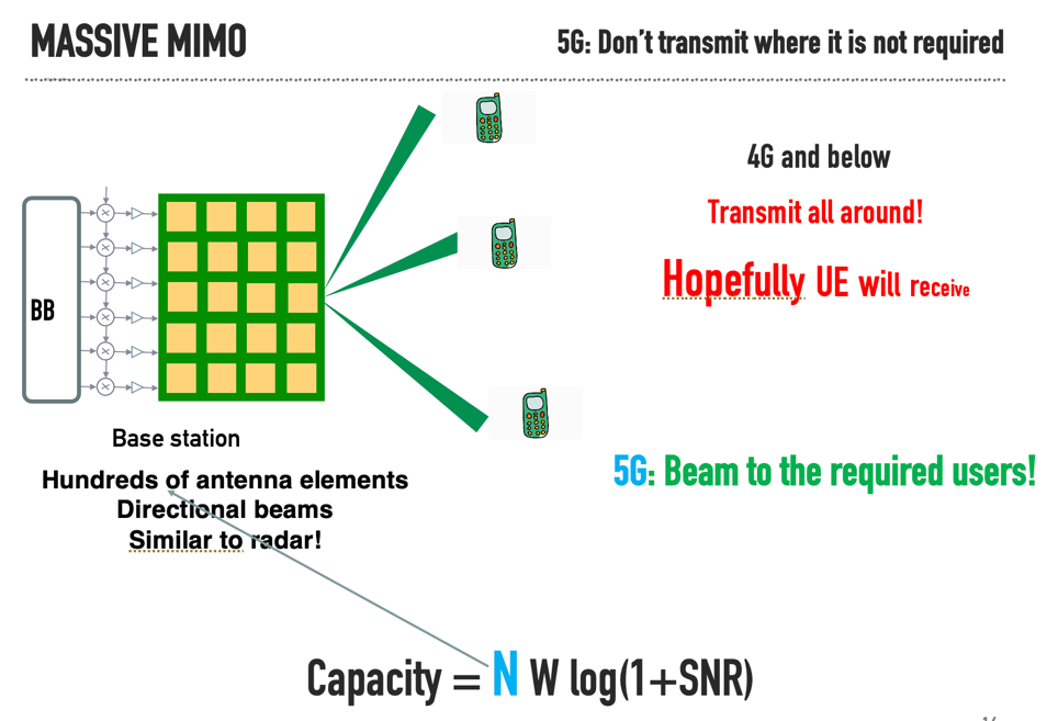
The “capacity” of a channel is the maximum number of bits that can be pushed into the channel per second and recovered reliably by the receiver. The maximum data rate (to some scaling) that can be transmitted by the base station with a single antenna is proportional to
C = W x log(1+SNR),
where W is the BW of the channel and SNR is the signal-to-noise ratio at the receiver. Most of the data-rate increase (from 2G3G4G) has been due to increasing the bandwidth W with each generation and we observe that this growth is linear with W. The SNR can be increased by reducing the cell size or increasing the TX power, but the capacity gains are only modest since the growth is logarithmic with respect to SNR. However, the amount of spectrum that can be allocated to a single operator is limited (at least in the sub-6 GHz range) and cannot increase without bounds. The maximum spectrum per channel has increased five-fold from 20 MHz in LTE to 100 MHz in 5G. From the above formula, we see that this would lead to a modest 5X gain in capacity of the cell. However, this is not sufficient to meet the 5G throughput demands. How can the capacity be increased for a fixed BW and SNR? It turns out that when the BS has multiple antennae, the above formula can be modified as
C =N x W x log(1+SNR),
where N is the number of antennae at the base station. This provides a new spatial dimension, namely the number of antennae, that can be explored to enhance the cell capacity. The increased data rate happens because independent streams of information can be sent across the antennas. Since this is a wireless medium, the various streams of data sent parallelly on the different antennas will interfere with each other and must be separated in the receiver. The MIMO (Multiple-Input Multiple-output) system innovation lies in the algorithms and reference signals that help in separation of these streams at the receiver with reasonable complexity.
To separate these multiple streams of data at the receiver, the knowledge of the wireless medium (channel) is required at the receiver. In a single antenna system, there is only one channel between the transmitter and the receiver, and this channel information is learned by the protocol by sending known (both at the transmitter and the receiver) wireless signals called pilots. In a MIMO system, the channels between each transmitter antenna and receiver antenna constitutes a channel have to be learned. Newer pilot designs (remember that these pilots are also part of the OFDM waveform, transmitted wirelessly and hence interfere with each other) are required so that the MIMO channel can be estimated at the receiver. This multi-port pilot design should be carefully done to not-increase the pilot overhead with increasing antenna configurations. In most cases, this channel knowledge is used to equalize the effect of the wireless channel at the receiver and recover the data.
Sometimes, this channel information is fed-back to the base station and the base station pre-compensates for the channel response before transmitting to the cellphones. This is called MIMO precoding and increases the obtained throughput (compared to the case where the channel is compensated only at the receiver). Precoding also helps in serving multiple users in the same time-frequency resources by separating them in the beam domain (also called as multi-user MIMO).
In 5G, twelve simultaneous streams of data are supported with various antenna configurations. For example, 16, 32 and 64 transmitter receiver chain configurations are very popular. One thing to keep in mind is that the size of the antenna depends on the frequency of operations. To reduce the correlation between antennas, the antenna elements are regularly placed with a distance greater than half the wavelength. For example, at 3.5 GHz (band n78), the distance between elements is approximately 4 cm, and a panel of 8×8 antennas would be at least 40 x 40 cm. This size would increase by 5 times for a 700 MHz panel which leads to mechanical stability challenges (weight and size) for deployments. Hence, while the standard supports Massive MIMO at all frequencies, MIMO solutions are generally popular for higher frequencies like 3.5 GHz.
In addition to providing higher data rates, massive MIMO solutions also provides beamforming gains. In 4G systems (with few antennas), the signal is transmitted in all the directions irrespective of the UE location, leading to unnecessary wastage of power. However, in massive MIMO systems, the signal beams can be pinpointed to the UE for which the signal was intended to, and this technique is called as beamforming . This would increase the signal-to-noise ratio of the 5G user and reduce radiation in all the un-necessary directions. The beamforming becomes better when the number of antennas increase, which is precisely the case in 5G. However, this leads to problems like initial access (in which direction do you do you point your narrow beam initially when you don’t know where the UE is) and the 5G standard takes care of these issues through beam access protocols. This leads to a more energy efficient network.
Massive MIMO forms the bedrock on which the higher throughput solutions of 5G are build. 5G standard provides the signal and pilot framework for implementing massive MIMO solutions. Great care was taken to limit the overhead of the pilots and make sure that the solution scales with increasing data streams and pilots. Also, the protocol can gracefully handle the channel feedback from the cellphones to the base station in the case of closed loop MIMO.
In the next post, we will look at the other three important technologies which drive 5G RAN.
